
-

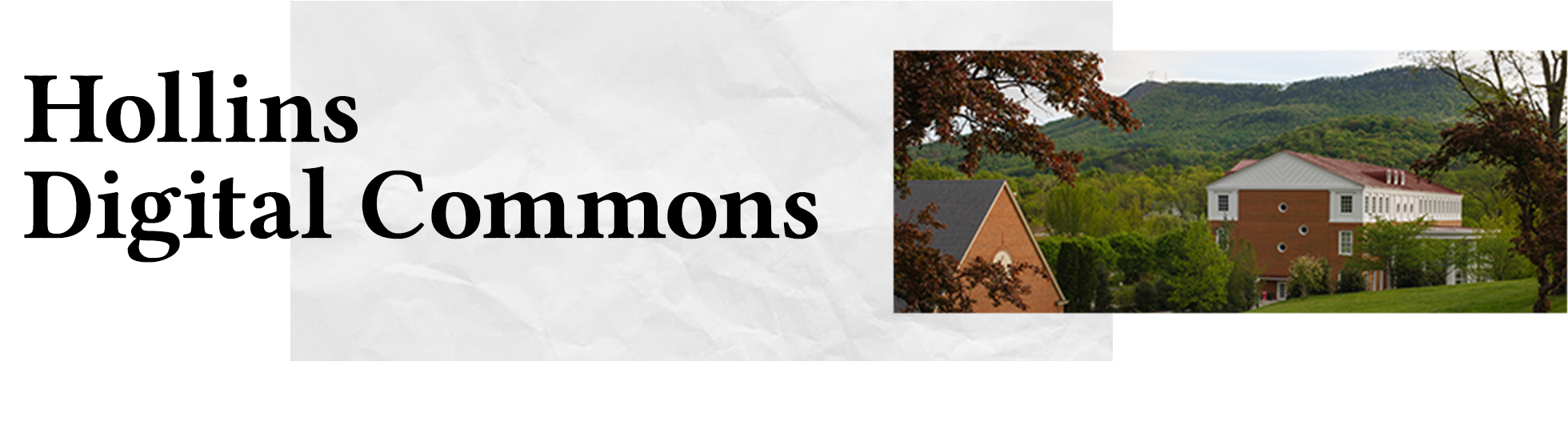
Bausch & Lomb Stereozoom 5 Microscopes
Natalie E. Owens
The Bausch & Lomb StereoZoom 5 Microscope was manufactured around 1976. This microscope is intended for use with three-dimensional objects rather than traditional laboratory slides. StereoZoom 5 models have magnification from 0.8x – 4.0x and can be used to study a variety of organic and inorganic materials. A lamp is paired with the microscope as a source of illumination. The two eyepieces on the microscope can be moved closer together or farther apart. A dial on the top of the apparatus is used to adjust the zoom level of the scope. This affects the depth at which the lens focuses. Two knobs on the sides of the supporting rod are used for lowering and raising the scope attachment. A knob at the bottom of the base rotates a mirror which is used to reflect light onto the subject.
-

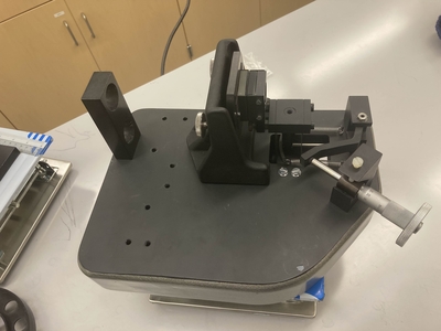
Beck Interferometer - Fabry-Pérot Configuration
Natalie E. Owens
Interferometers are devices used to study electromagnetic waves through the use of wave interference. The Beck – Ealing 25 - 700 Interferometer can be configured to use Michelson or Fabry-Pérot methods for studying interference between waves. This interferometer was created in England by R & J Beck LTD, an optical company that is now under the ownership of Beck Optronic Solutions Ltd. The device we have appears to be mostly intact with a few parts missing. The parts missing include a few legs which screw into the bottom of the device, the 6281 and 6281A twin tungsten and mercury lamps, the 6290-gas cell, the 6294-needle valve, the 6289-manometer, and the 6288-vacuum pump. The gas cell, needle valve, manometer, and vacuum pump were once used to analyze the speed of light through a vacuum. The tungsten and mercury lamps are not a necessity for using the device; a typical helium-neon laser suffices for the Michelson configuration; however, a diffused light source is best for the Fabry-Pérot configuration.
The Fabry-Pérot configuration is achieved through placing two parallel mirrors within micrometers of each other with their reflective surfaces facing together. One mirror can be moved forward and backwards through an adjustable knob, with distance measured in micrometers. A light source, such as a sodium lamp, is passed through a collimating lens to converge the light onto the middle of the mirrors. The two mirrors reflect the beam multiple times and onto a surface, where an interference fringe can be observed.
-

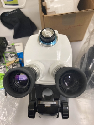
Beck Interferometer - Michelson Configuration
Natalie E. Owens
Refer to the entry on the Fabry-Pérot configuration for information on the Beck - Ealing Interferometer itself.
The Michelson configuration in optical interferometry involves one source of light being divided into two waves by a beam splitter, and recombined through reflection off of two mirrors into the same beam splitter. The result is an interference pattern between the two waves due to them originating from the same source and reflecting onto the same point on a surface. The stationary mirror typically needs to be adjusted so that both light beams overlap at the same point. A movable mirror can be brought forward and backward in micrometers, which causes a change in pathlength for one of the beams. This causes the interference pattern to shift between constructive and destructive patterns.
-

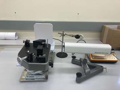
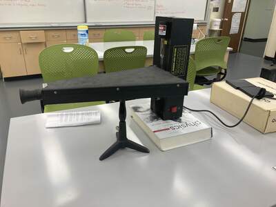
W.M. Welch Scientific Company Grating Spectrometer
Natalie E. Owens
The W.M. Welch Scientific Company grating spectrometer, No. 3693, was manufactured around the 1950s. A light source can be placed at the slit near the wider end, by which it will illuminate a graduation scale, measured in angstroms, inside of the device. The width of the slit can be adjusted using the silver knob attached to the back of the spectrometer. A small reading light can be attached to the clamp between the scale and the slit for the purpose of making the scale easier to view. When looking through the scope, you will see the first-order spectrum of the light source appear on a marked scale to the right, allowing you to view the distance between the fringes.
The spectrometer can be calibrated using a known light source, such as helium. Place a helium light source in front of the slit on the back of the spectrometer. Look through the scope. You should see a yellow fringe between the 58 and 59 angstrom line. The slit may need to be adjusted in width depending on the strength of the light source. If the yellow fringe is not in this position, then the eye piece of the scope may need to be adjusted. Consult the digitized manual for instructions on this process.
-

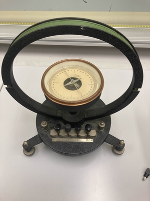
CENCO Tangent Galvanometer
Natalie E. Owens
The CENCO Tangent Galvanometer is a vintage piece of scientific equipment that is used to measure electric current that is run through the device. Compared to other tangent galvanometers of the time, this device has removable switches that changes the number of resistors the current runs through. Other galvanometers of the time typically had multiple ports to run the electrical current through that would put the current into a different number of coils. To derive a value for the current ( "I") using the tangent galvanometer, first make sure the compass is pointing towards zero. When the compass is properly aligned, you may run the current through the two, non-numbered ports. The needle of the compass will deflect from zero to an angle that is proportional to the electrical current. Then, use the formula tanθ=B/BH.
Printing is not supported at the primary Gallery Thumbnail page. Please first navigate to a specific Image before printing.